
|
Of This Page Reflectron TOF (RETOF) (oaTOF) |
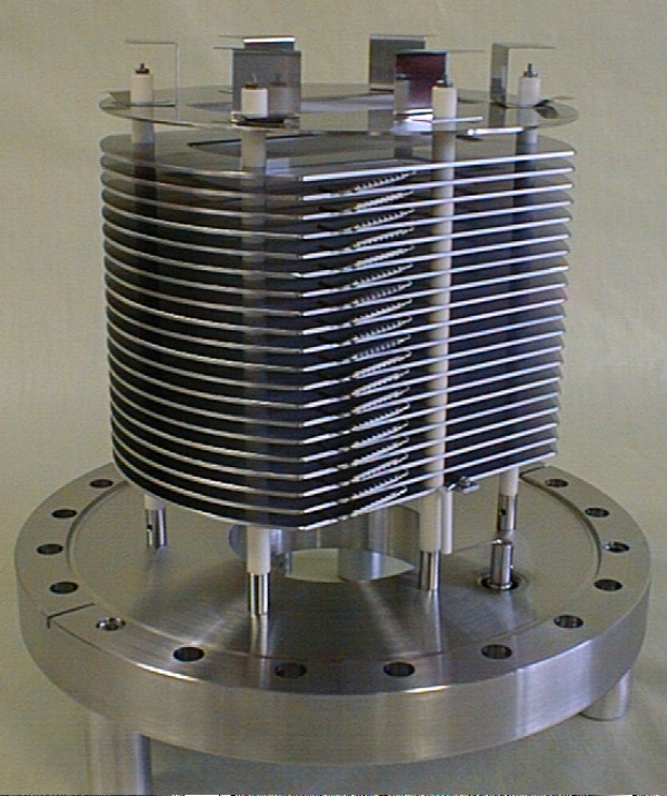
(Click image to enlarge)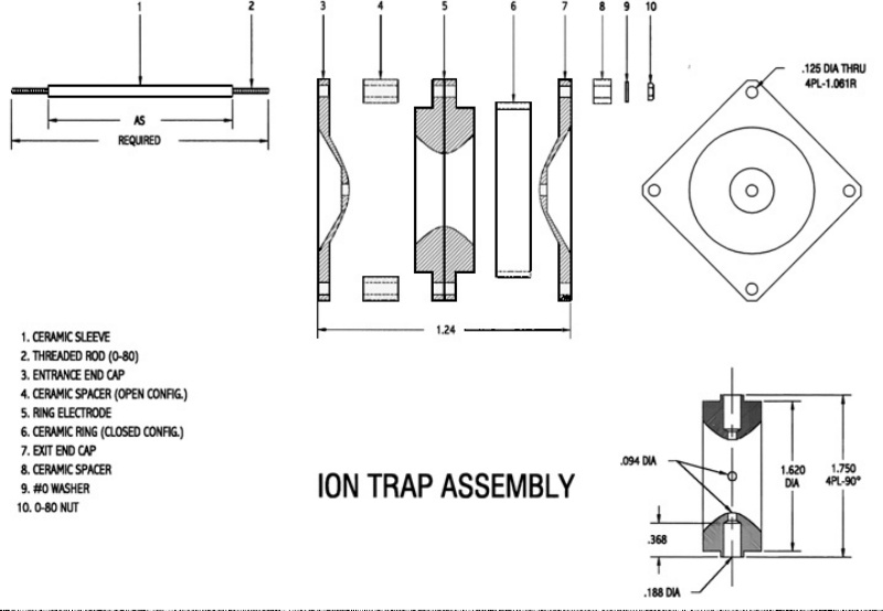 Illustration of Ion Trap Assembly |
C-1251 QUADRUPOLE ION TRAP C-1251Designed to enhance the sensitivity and versatility of our TOFMS instruments by providing long term ion storage in the source region. A drawback of TOF devices is the lack of a means of storing ions prior to analysis. This inability to store ions compared to trap methods such as FTICR and ITMS place TOF at a disadvantage in terms of being able to manipulate ions for MS/MS or ion-molecule experiments, or for enhancing sensitivity through storage and integration of the signal. The QUADRUPOLE ION TRAP can be used to overcome these limitations. Ions can be created and stored during the time between extraction pulses. Approximately 125 microseconds are required for Ion extraction and return to trapping RF potential. It can be seen that duty cycle approaches 100% for storage times of over 10 milliseconds. |
||
|
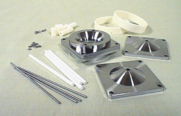
The mechanical assembly is 1.75 in. square by 1.25 in. high and is machined to mount to our standard ion source. One end cap is center bored with a choice of diameters. This opening is covered with a 90% transparency mesh to provide an extraction grid. The opposing end cap can be bored for injection of ions or electrons if desired. The center ring can be bored and cross bored for passage of laser beams, molecular beams, sample probes, etc. |
||||
| The elements of the assembly are held together with through bolts and ceramic spacers. Ceramic sealing rings can be added if desired in order to contain neutral species (buffer gas), increase local pressure inside the trap or prevent back migration of unwanted species into the trap. Materials of construction are 304 Stainless Steel and Alumina. The assembly can be installed at the time of manufacture of a TOF or retrofitted to most instruments manufactured by us. | ||||
D-1203 ION TRAP POWER SUPPLYThis power supply was designed to provide RF voltage to the C-1251 Ion Trap. Following is a brief description. Size (approximately), rack mounted. 19"W
x 7"H x 16"D The D-1203 Ion Trap Power Supply has the ability to operate at bias voltages of up to 3500V, adding experimental flexibility. The D-1203 Ion Trap Power Supply comes equipped
with a power meter which reads the power required to drive the
C-1251 Quadrupole Ion Trap. It also has two LED's which indicate
excess power consumption. One of these is fixed and will light
at 50 watts power consumption. The sensitivity of the other one
can be adjusted by the user to indicate a dirty trap or excess
gas pressure. |
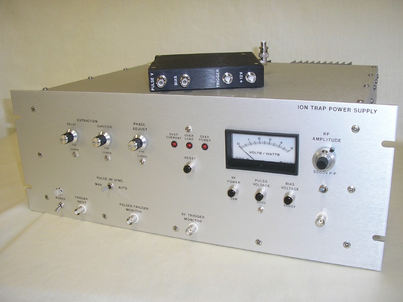 D-1203 Ion Trap Power Supply and D-1040 H.V. Pulser |
||
|
The D-1203 Ion Trap Power Supply contains the pulse voltage power supply to drive the D-1040 Remote Pulser. It controls the storage time and extraction pulse timing, and shut-off of the RF. The extraction pulse can also be synchronized with the RF phase. This is valuable when extracting ions with the RF turned on (a way to increase the duty cycle and/or repetition rate). RF voltage can be shut down in ½-cycle at 750V and 2 cycles at 3000V RF. |
|||
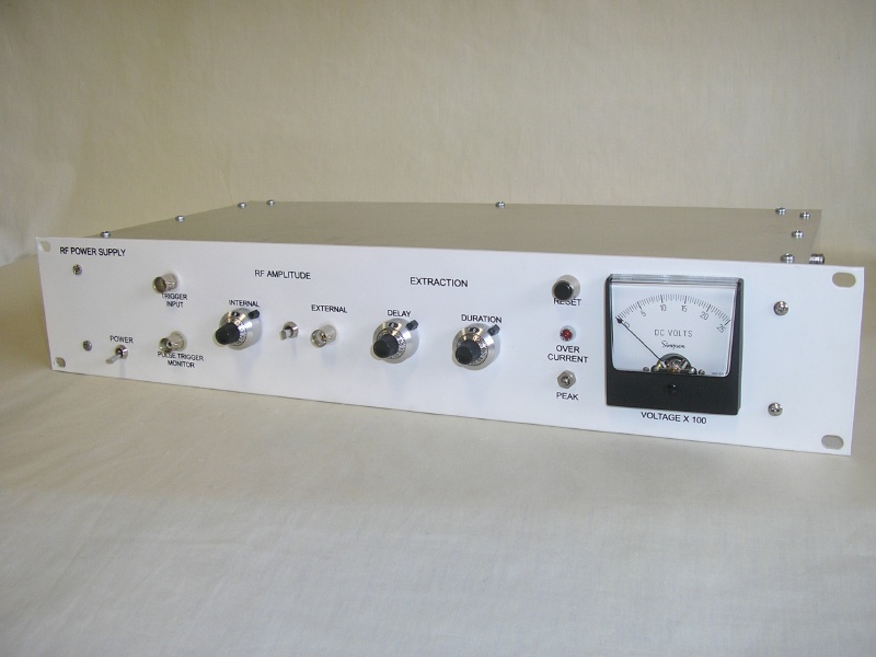 D-1230 RF Power Supply |
D-1230 RF POWER SUPPLYThis power supply was designed to provide RF voltage to the C-1251 Quadrupole Ion Trap. It is a lower cost, lower power version of the D-1203. It cannot be floated and has no driver for the pulser. It is designed to be used either with either a D-1050 dual output high voltage pulser or our D-1040 Pulser and D-1003 Power Supply. Following is a brief description. Size (approximately), rack mounted. 19"W
x 3.5"H x 8"D Must be operated with the furnished RF output cable which is five feet long. For economic reasons, the complexity of the unit was strictly controlled. No elements were included which were not absolutely necessary. |
||
|
The following is just one of many possible operation modes. 2500V. RF at 1 MHz is applied to the ring by the D-1230 RF Power Supply. Ions can now be generated inside the trap, or created externally, then injected into the trap through the end cap. They will remain in the trap under these conditions for as long as two seconds. When the RF Power Supply receives a TTL trigger
pulse from a computer or some other external source, it shuts
down the RF This can be repeated up to 10,000 times per second with 97 microsecond storage time. Spectra will not overlap up to m/e=500 when used with our AREF (D-850) and these input conditions. It should be noted and emphasized that this equipment was designed for pulsed extraction into a TOFMS or similar experiment. It will not work in the usual "mass selective instability" mode. |
|||
|
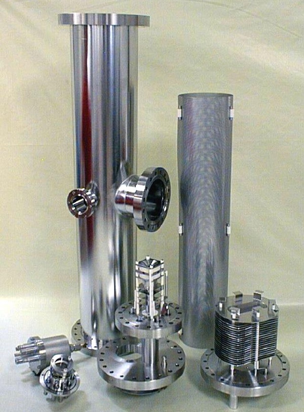
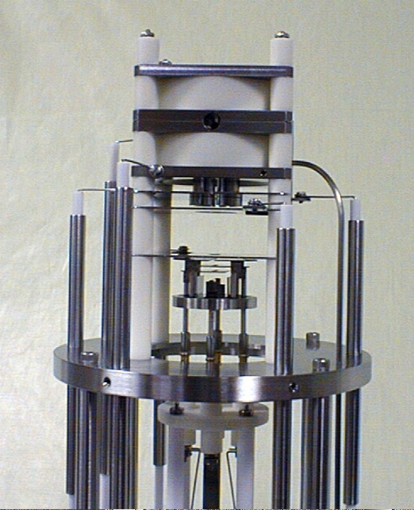
C-1470 ION TRAP EXTRACTION OPTICS A system of grids, tubes and apertures which shield, focus and isolate the extracted ion packets between the ion trap and the flight tube. The design of this assembly is critical due to the large difference between pressures in the Ion Trap and the Flight Tube. Each application is individually engineered. One of many possible configurations of an ion generation/storage device. The assembly consists of the C-950 EGUN and C-1251 Ion Trap mounted on a 6 inch or larger flange. Ions can be pulsed from this device directly through an acceleration grid and into a flight tube for mass separation and analysis. Ions are generated in the space between the plates which separate the EGUN and Ion Trap. They can be created by electron bombardment and/or laser excitation. |
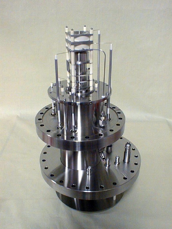
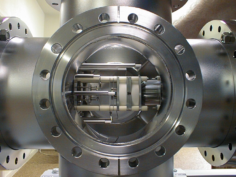 C-1550 Ion Trap EGUN Mounted on D-1450 ITRETOF |
||
 C-1550 Ion Trap EGUN Illustration |
The ions are then extracted and focused through the end cap aperture, into the ion trap. Use of a split Einsel tube allows some correction for initial molecular beam velocity as well as providing ion transport. The voltage on one of the tube halves can be stepped for gating purposes. The components are mounted on insulators so that the entire assembly can be operated at elevated potential. In this case, guard rings would be needed around the trap to minimize ion leakage. All our relevant power supplies are capable of being biased to 3.5KV for this purpose. A tube is provided through the flange for introduction of helium or other buffer gas. The 6.0 inch dimension shown is standard protrusion. Other lengths can be provided to adapt to chamber dimensions and beam geometry. |
||
|
D-803i ION TRAP REFLECTRON POWER SUPPLY Size (approximately), rack mounted. 19"W
x 5.25"H x 14.5"D This (ITAR) Ion Trap Angular Reflectron Power Supply has been designed for use with our D-850I Ion Trap Angular Reflectron Time Of Flight. All voltages are monitored by the same meter, which only displays a voltage when a monitor button is held down. Each end of every cable is labeled to match the receptacle to which it connects. D-803i Ion Trap Reflectron Power Supply Literature
(PDF) |
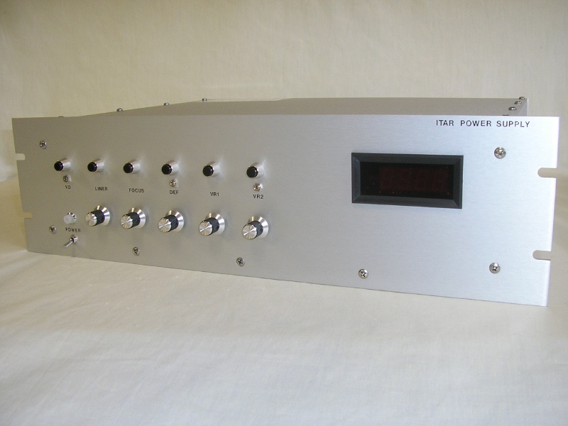 D-803i Ion Trap RETOF Power Supply |
||
|
|
Description of Images and Product Information Downloads: | |||
 |
 |
Ion Trap Time Of Flight Mass Spectrometers: Smaller Geometry Ion Trap Reflectron Mass
Spectrometer (left) Small Geometry Ion Trap Reflectron Product Information |
||
 |
 |
D-1452 Reflector Assembly for Smaller Geometry
ITRETOF (left) |
||
 |
 |
C-1454 Offset Adaptor Assembly for Smaller
Geometry ITRETOF (left) |
||
|
|
||||
|
User Manuals: |
||||
|
|
|
|
|
|